


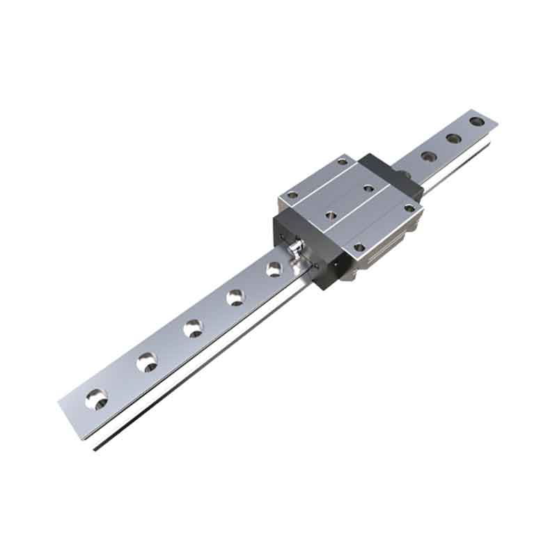
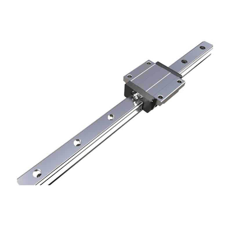
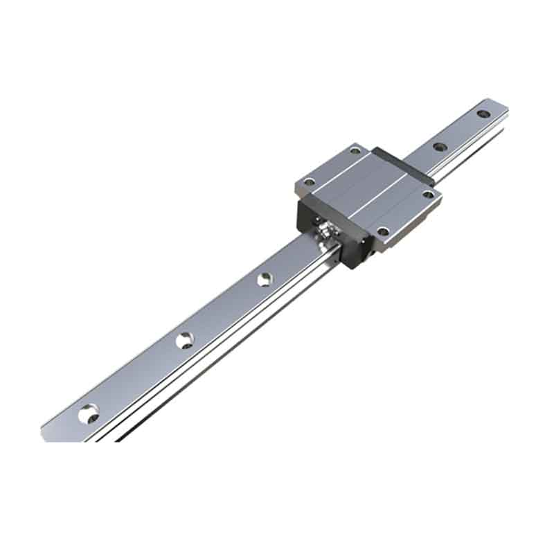
Linear guide CMGN-R / CMGN-LR
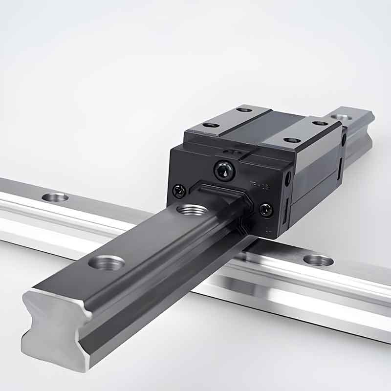
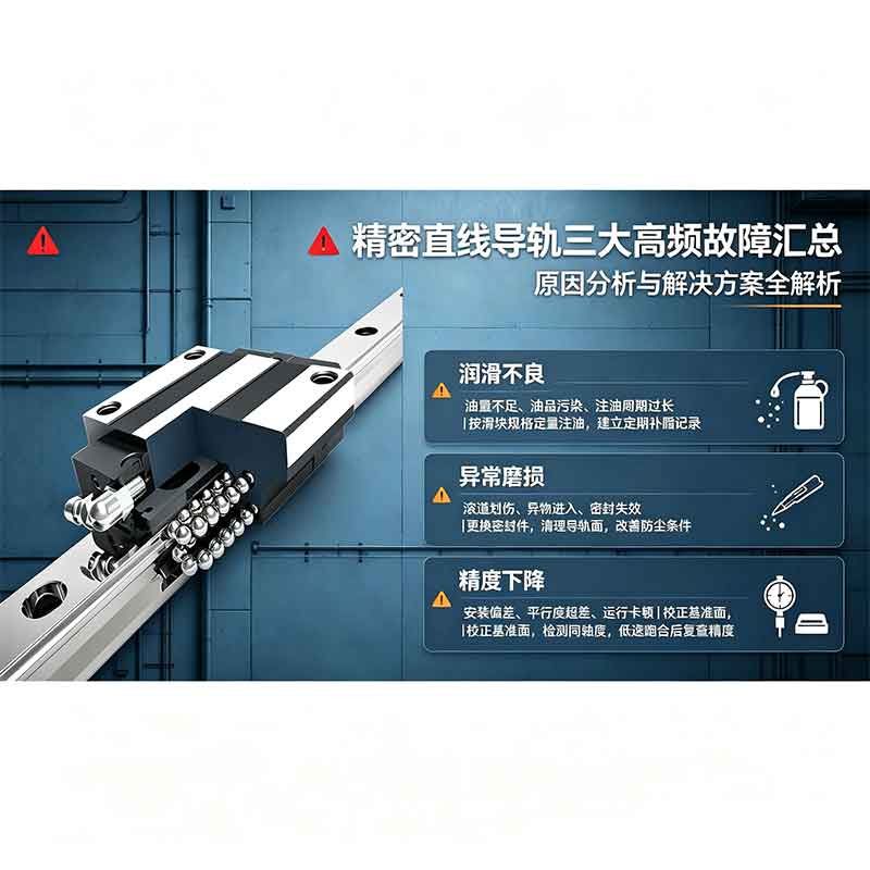
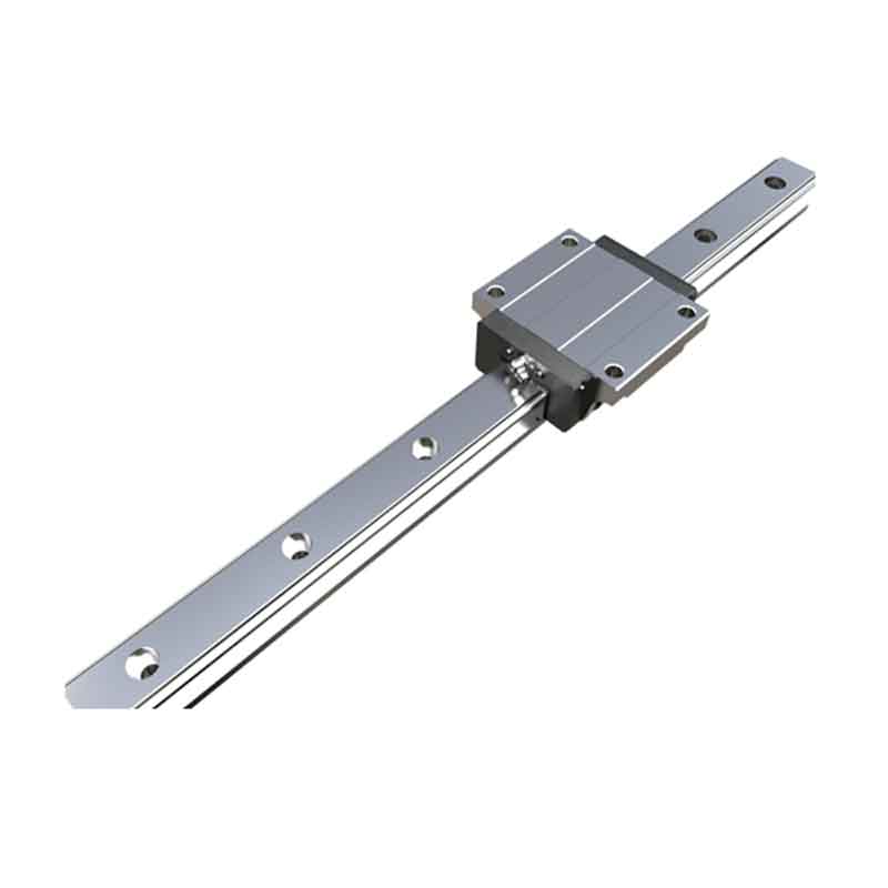
CRK precision linear guides are key guide components for high-end intelligent manufacturing equipment.
Description
marker
Characteristics
1. Self-installation ability
Thanks to the combination of DF type arc grooves (45°–45°), elastic deformation of the balls and displacement of the contact points, a self-aligning effect is achieved. Even if there are certain deviations in the mounting surface, they are absorbed inside the guide pair, providing highly accurate, smooth and stable linear movement.
2. High rigidity in all directions
CHH/CHHP series guide pairs use a four-row arc groove design with a 45° ball contact angle in each groove. This ensures that the CHH/CHHP carriage has equal load ratings in four directions and, if necessary, sufficient preload can be applied to increase rigidity.
3. Superior durability
Even under preload or eccentric loading, the balls experience only slight differential slip, resulting in extremely low sliding friction. This ensures long-term preservation of high wear resistance and stability of accuracy.
4. High tightness
The CHH/CHHP series guide pairs can be equipped with a variety of seals to enhance sealing properties, making them particularly suitable for use in dusty or wood chip environments.
Product Description
CRK precision linear guides are key guide components for high-end intelligent manufacturing equipment. Relying on the proven four-directional constant motion load design and precision grinding technology, they combine high precision, high rigidity, low friction and high adaptability. This series is widely used in high-precision operating environments, including precision machine tools, semiconductor equipment, new energy automation and precision instrumentation, making it the optimal guide component for industrial high-precision linear motion.
The key advantages of this series of guides are precision stability, load balance and smooth running. The guides are made of high-quality alloy steel with general hardening and ultra-fine grinding. The raceways have a uniform and ordered surface structure. Dimensional tolerances and parallelism of stroke are controlled with high rigor. Accuracy classes available: standard, precision and ultra-precision. Combined with standard preload, operating gaps are completely eliminated, and deviations during reverse and jamming during microfeeds are effectively prevented. There is no creep at low speeds, micrometric repeatability of positioning is achieved, which fully satisfies the stringent requirements of precision machining and micro-measurements.
In terms of performance and durability, CRK guides have a four-directional equal-motion load capacity, evenly distributing radial and lateral forces. They demonstrate high resistance to deformation and shock loads, have high rigidity and stability, and are suitable for high-speed feeds and 24-hour continuous operation. The friction coefficient is extremely low, the moving resistance is low, and the response is fast, which can effectively reduce equipment energy consumption and noise levels. Additionally, they are equipped with an integrated multi-layer dust sealing system that effectively prevents chips, dust and moisture from entering the raceways, allowing them to adapt to harsh operating environments including shop processing and cleanrooms, significantly reducing wear and failure.
Relying on strict ISO quality control system and high-precision production technology, CRK precision guides feature high parameter reproducibility and good interchangeability. Installation and commissioning are simple and convenient; it can be used with modules of various sizes. Overall service life is increased and maintenance costs are reduced. Combining precision, stability and practicality, as well as value for money, CRK guides provide reliable and stable linear guidance for a wide range of high-end automated precision equipment.
Applications
Construction machinery, material feeders, electrical discharge machines, laser processing equipment, machining centers, CNC machines, industrial robots, packaging equipment and others.
Product Features
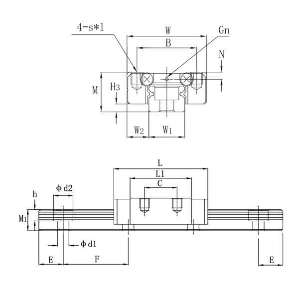
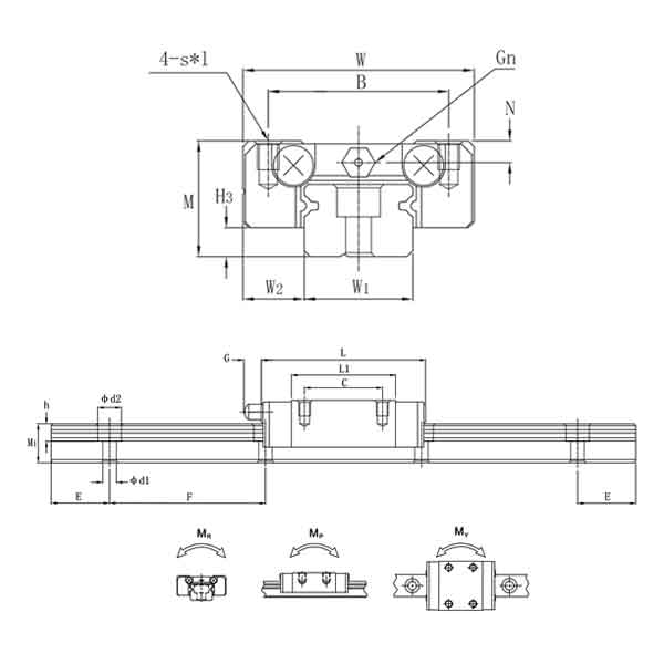
| Model | Dimensions (mm) | Carriage dimensions (mm) | H3 | Guide Dimensions (mm) | Bolts for fastening guides | Basic dynamic and static load capacities | Permissible static moment | Carriage weight, kg | |||||||||||||||||
| Height M | Width W | Length L | B | C | Sxl | L1 | N | G | Gn | Width W₁ | W2 | Height M₁ | Hole spacing F | Distance between ends E | d1xd2xh | C (dyn.) kN | C₀ (stat.) kN | M.R. N·m | MP N·m | M.Y. N·m | Carriage weight, kg | Guide weight, kg/m | |||
| CMGN 7R | 8 | 17 | 22.5 | 12 | 8 | M2x2.5 | 13.5 | 1.5 | - | φ1,2 | 1.5 | 7 | 5 | 4.8 | 15 | 5 | 2.4x4.2x2.3 | M2x6 | 0.97 | 1.22 | 4.69 | 2.84 | 2.84 | 0.01 | 0.22 |
| CMGN 7LR | 8 | 17 | 30.8 | 12 | 13 | M2x2.5 | 21.8 | 1.5 | - | φ1,2 | 1.5 | 7 | 5 | 4.8 | 15 | 5 | 2.4x4.2x2.3 | M2x6 | 1.36 | 1.95 | 7.61 | 4.81 | 4.81 | 0.015 | 0.22 |
| CMGN 9R | 10 | 20 | 28.9 | 15 | 10 | M3x3 | 18.9 | 1.8 | - | φ1.4 | 2 | 9 | 5.5 | 6.5 | 20 | 7.5 | 3.5x6x3.5 | M3x8 | 1.88 | 2.54 | 11.75 | 7.36 | 7.36 | 0.016 | 0.38 |
| CMGN 9LR | 10 | 20 | 39.9 | 15 | 16 | M3x3 | 29.9 | 1.8 | - | φ1.4 | 2 | 9 | 5.5 | 6.5 | 20 | 7.5 | 3.5x6x3.5 | M3x8 | 2.54 | 4.03 | 19.58 | 18.61 | 18.61 | 0.026 | 0.38 |
| CMGN 12R | 13 | 27 | 34.7 | 20 | 15 | M3x3.5 | 21.7 | 2.5 | - | φ2 | 3 | 12 | 7.5 | 8 | 25 | 10 | 3.5x6x4.5 | M3x8 | 2.82 | 3.93 | 25.48 | 13.72 | 14.72 | 0.034 | 0.65 |
| CMGN 12LR | 13 | 27 | 45.4 | 20 | 20 | M3x3.5 | 32.4 | 2.5 | - | φ2 | 3 | 12 | 7.5 | 8 | 25 | 10 | 3.5x6x4.5 | M3x8 | 3.75 | 5.88 | 38.23 | 36.25 | 36.25 | 0.054 | 0.65 |
| CMGN 15R | 16 | 32 | 42.1 | 25 | 20 | M3x4 | 26.7 | 3 | 4.5 | M3 | 4 | 15 | 8.5 | 10 | 40 | 15 | 3.5x6x4.5 | M3x10 | 4.62 | 5.58 | 45.06 | 21.51 | 21.51 | 0.059 | 1.06 |
| CMGN 15LR | 16 | 32 | 58.8 | 25 | 25 | M3x4 | 43.4 | 3 | 4.5 | M3 | 4 | 15 | 8.5 | 10 | 40 | 15 | 3.5x6x4.5 | M3x10 | 6.38 | 9.11 | 73.48 | 57.78 | 58.78 | 0.092 | 1.06 |
contact us
Related Popular Products
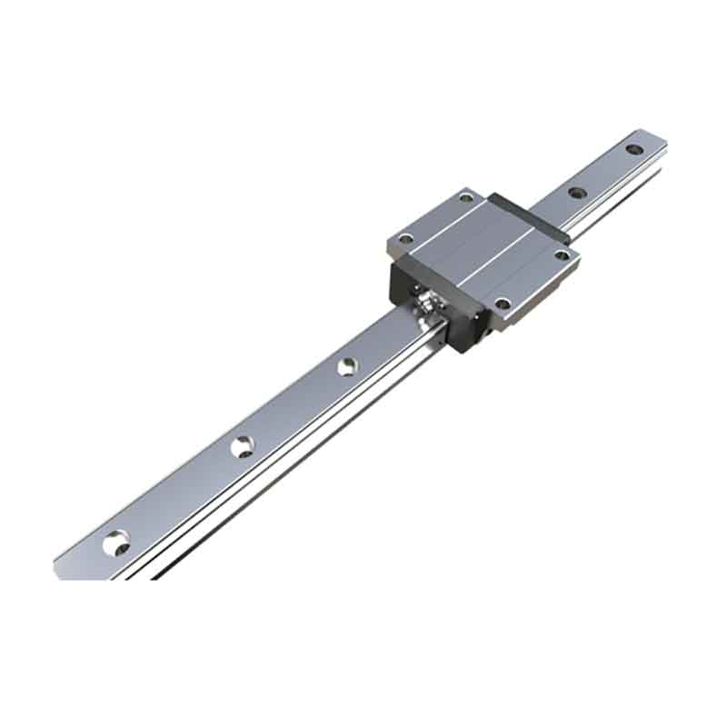
Linear guide CEG-SC / CEG-C
CRK precision linear guides are key guide components for high-end intelligent manufacturing equipment.
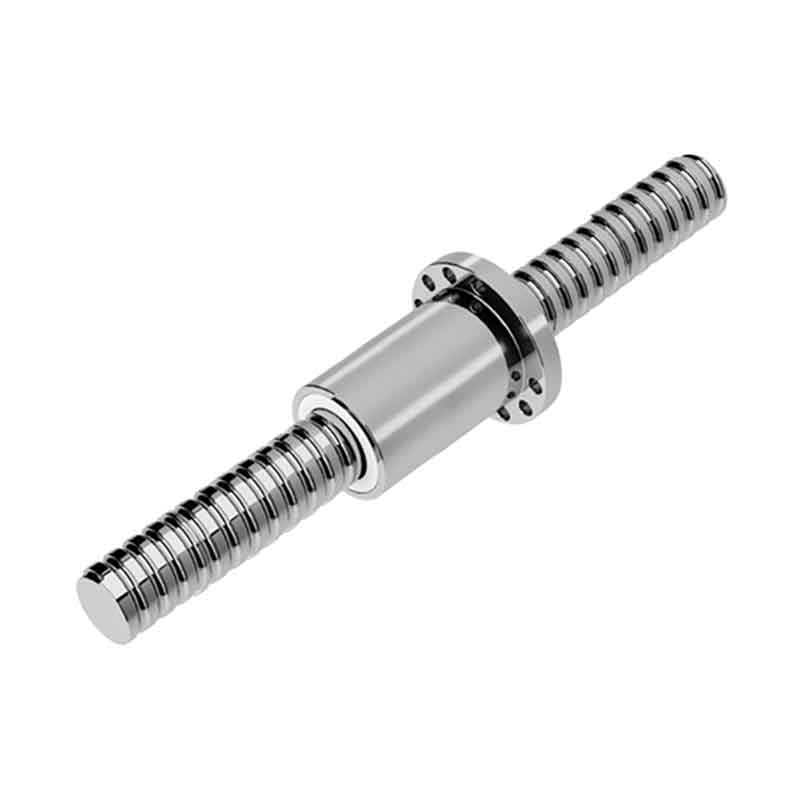
BBFS Ball Screw
CRK precision ball screws are key transmission components for high-end precision equipment.
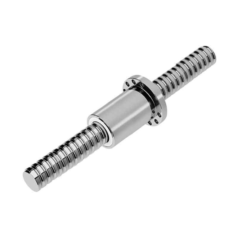
Ball Screw BGFS
CRK precision ball screws are key transmission components for high-end precision equipment.
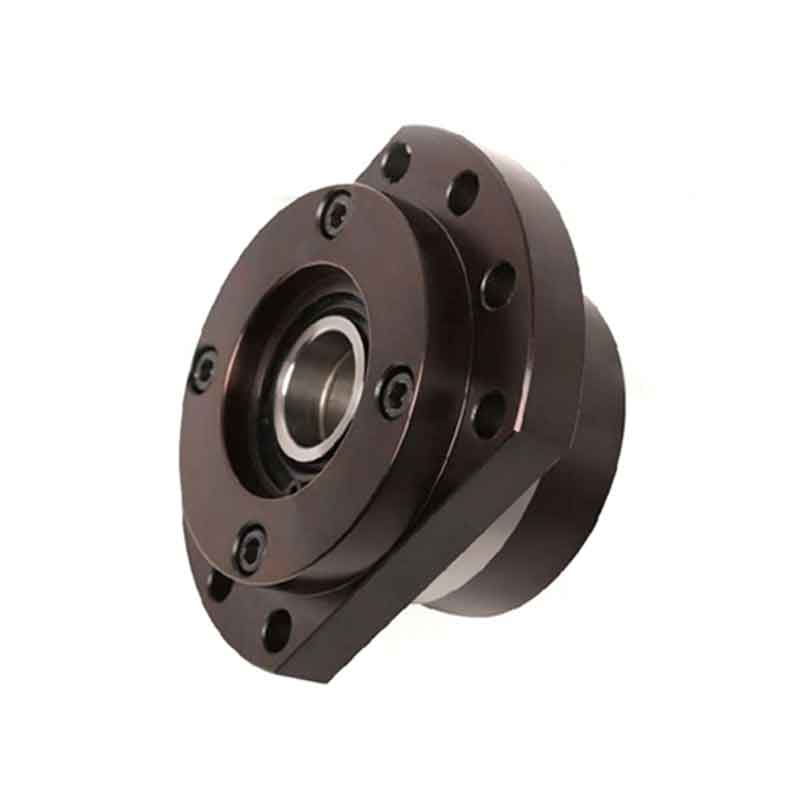
Support units with shaft type H (BK)
CRK ball screw support units are the key components of the ball screw transmission system.
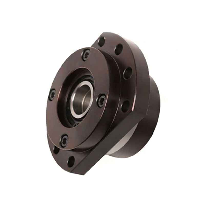
BK Series Fixed Side Support Units
CRK ball screw support units are the key components of the ball screw transmission system.
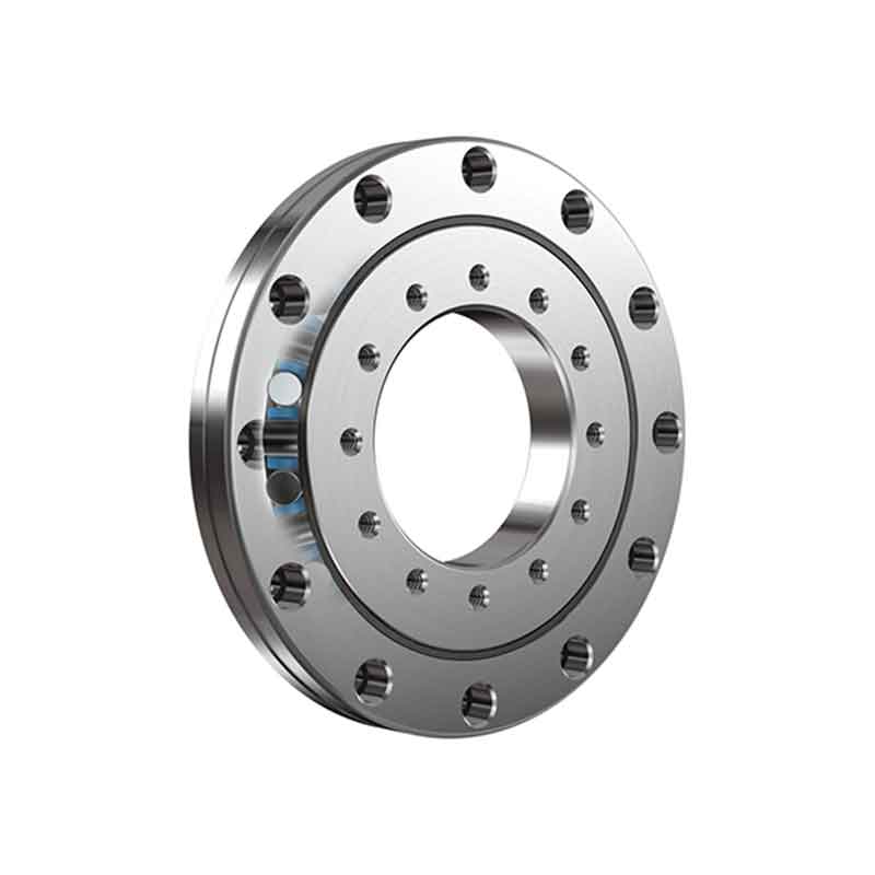
Cross roller bearing RA
CRK cross roller bearings have a compact integral design with a flange on both the inner and outer ring.
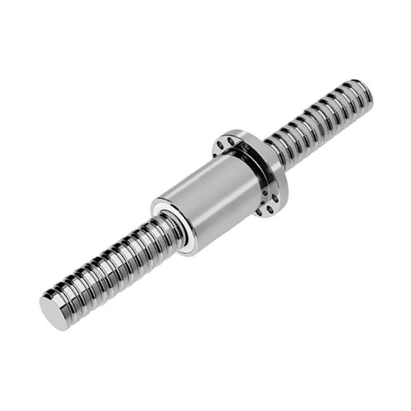
Rolled Series Ball Screw SCNI SCI
CRK precision ball screws are key transmission components for high-end precision equipment.
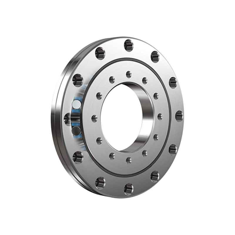
Cross roller bearing RU
CRK cross roller bearings have a compact integral design with a flange on both the inner and outer ring.
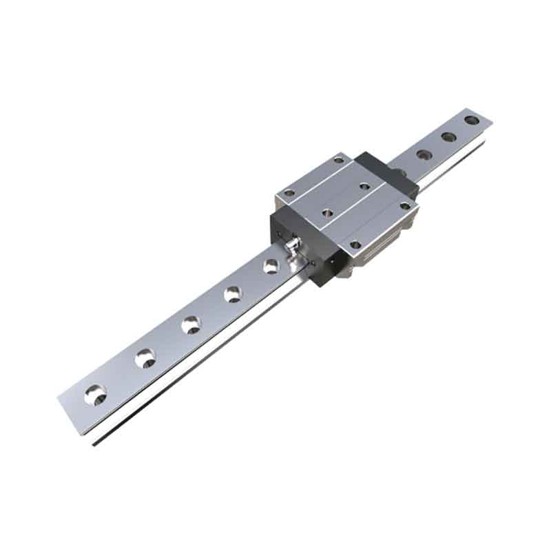
Linear slide CHR-C/CHR-LC
CRK precision linear guides are key guide components for high-end intelligent manufacturing equipment.
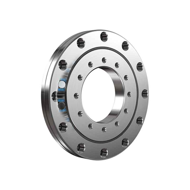
CRBT Cross Roller Bearing
CRK cross roller bearings have a compact integral design with a flange on both the inner and outer ring.
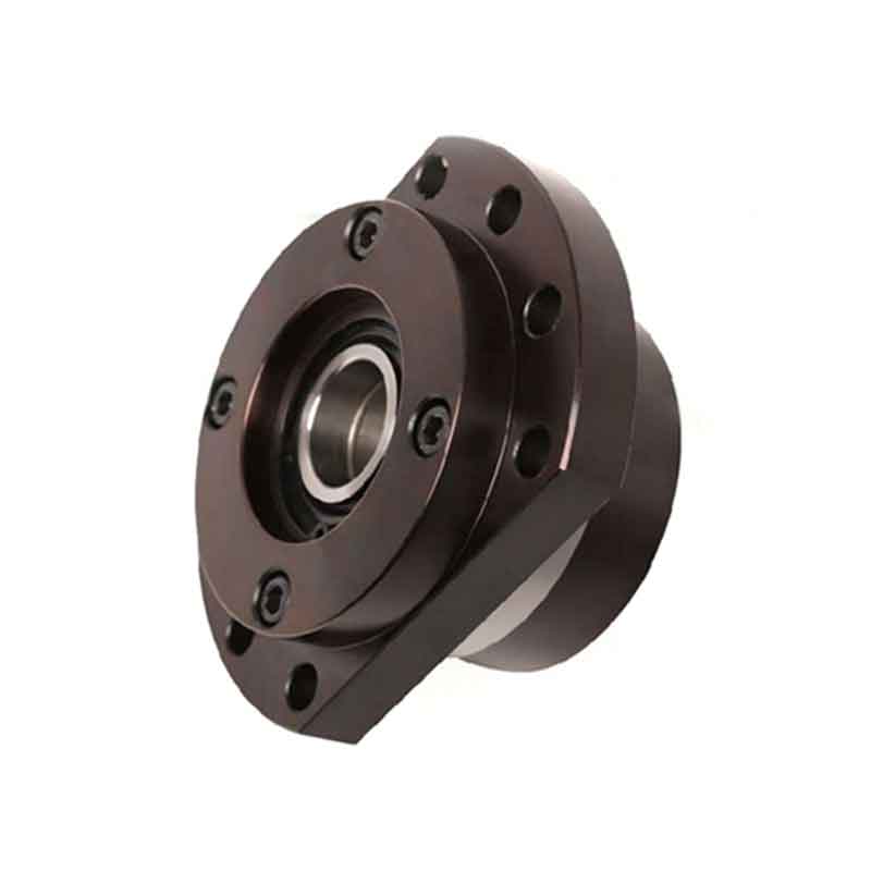
Series of support units FSK and FSKG, designed for machine tools
CRK ball screw support units are the key components of the ball screw transmission system.
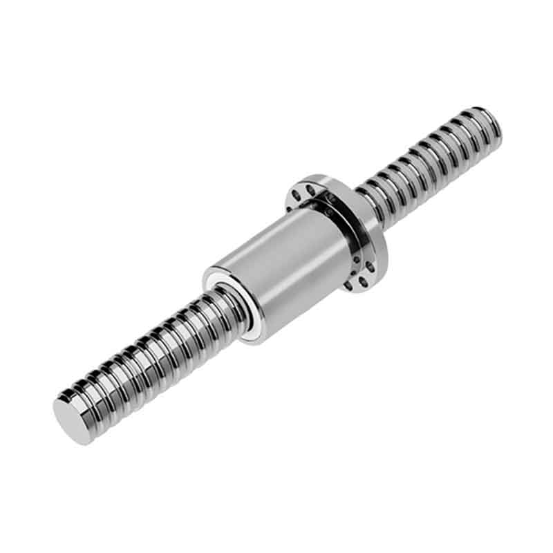
Rolled series ball screw SFV
CRK precision ball screws are key transmission components for high-end precision equipment.
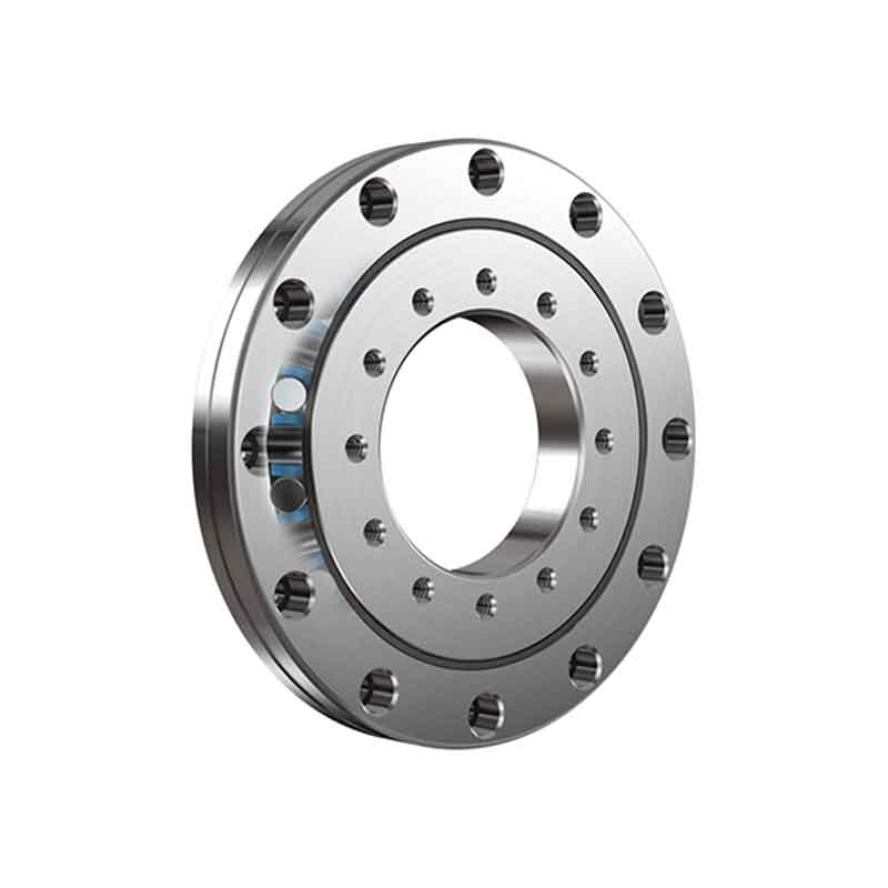
Cross roller bearing RB
CRK cross roller bearings have a compact integral design with a flange on both the inner and outer ring.
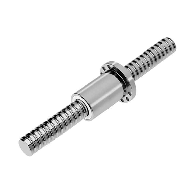
Rolled series SFY single pitch ball screw
CRK precision ball screws are key transmission components for high-end precision equipment.
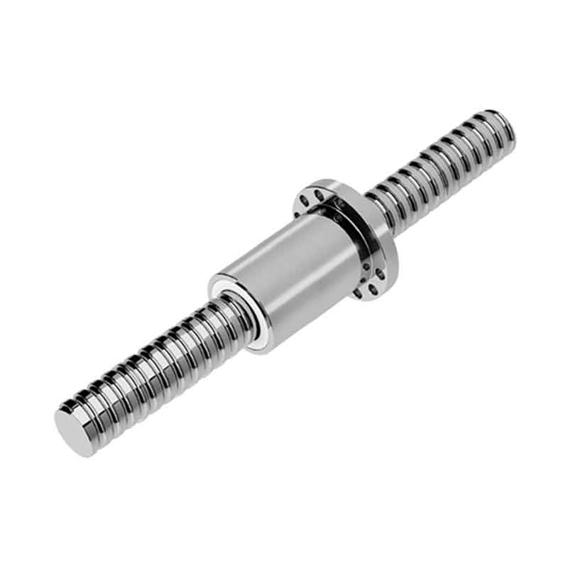
Ball Screw BGFD
CRK precision ball screws are key transmission components for high-end precision equipment.
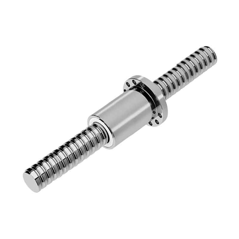
BDFS ball screw with reduced nut outer diameter
CRK precision ball screws are key transmission components for high-end precision equipment.


